


Ecotechnical Fish Migration Solution IV
The ecotechnical Solution IV for fish migration upstream and downstream from Romania’s Isalnita Dam involves creating an engineering system on the right bank of the Isalnita Lake. A mobile metal bar will be fixed to the right concrete bank at a 100 m distance from Isalnita Dam using metal hinges and a hydraulic telescopic cylinder-shaped piston (Fig. 1).
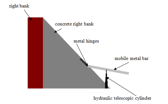
Image Courtesy of Razvan Voicu | Figure 1. Positioning the mobile metal bar – indicative scheme
A metal tank is attached to the end of the mobile metal bar. When the hydraulic telescopic cylinder is in minimum position, the metal tank is positioned inside Isalnita Lake (Fig. 2).
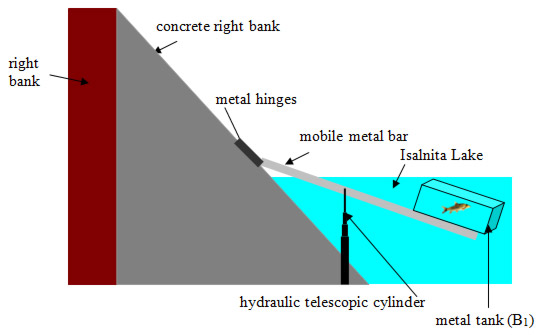
Image Courtesy of Razvan Voicu | Figure 2. Positioning the metal tank (B1)
Fish in Isalnita Lake that want to reach the sluices are directed by means of electric fields produced by generators fixed to poles. These metal or concrete poles are fixed to the banks of Isalnita Lake (Fig. 3). The poles are fixed to two lines forming an angle to 120 degrees.
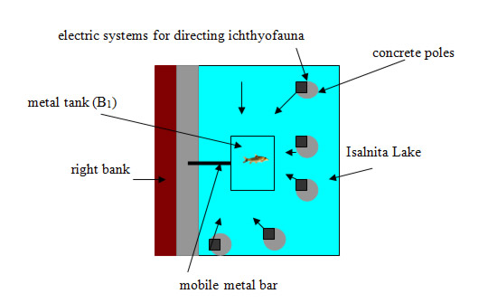
Image Courtesy of Razvan Voicu | Figure 3. Positioning the systems for directing the ichthyofauna
When the hydraulic telescopic cylinder starts to the maximum position on the upper surface of the tank (B1), there is a flexible rolled up grid closing the metal tank (B1) so that the ichthyofauna within this tank are captured inside. The hydraulic telescopic cylinder lifts the metal bar that supports the tank to the point where, due to gravity, the tank (B1) slides on the bar using the two metal rails (Fig. 4).
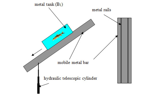
Image Courtesy of Razvan Voicu | Figure 4. Positioning the rails on the metal bar
All components are water resistant. A semicircular canal will be built into the lake bank in the same direction or on the same line with the metal bar in maximum position of tank sliding (Fig. 5). The impact between the metal tank and lake is almost entirely attenuated due to rubber drums positioned on the lake bank but also due to metal fixing systems (Fig. 5). After the metal fixing systems have been operated, they automatically engage the opening of a metal door belonging to the tank, which allows fish to reach the canal in the bank of Isalnita Lake (Fig. 6). On the right bank of the lake, near the underground canal built for taking over the ichthyofauna, another metal tank will be built (B2) having the approximate dimensions of 5x4x3m. The metal tank (B2) for ichthyofauna receiving in the underground canal will be fixed to a concrete foundation in the breakwater (Fig. 7).
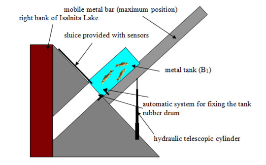
Image Courtesy of Razvan Voicu | Figure 5. Underground canal taking over the ichthyofauna from the metal tank for ichthyofauna transportation
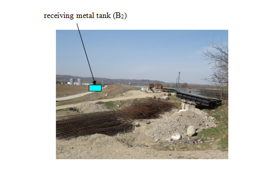
Image Courtesy of Razvan Voicu | Figure 6. Positioning the receiving metal tank (B2)
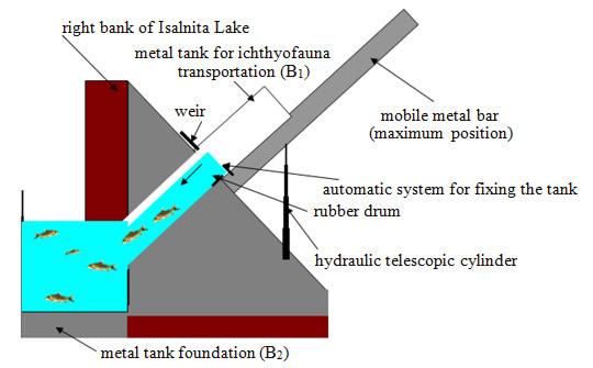
Image Courtesy of Razvan Voicu | Figure 7. Positioning the metal tank foundation for receiving ichthyofauna
The metal tank for receiving ichthyofauna will be supplied with water from upstream through a metal pipe. Its surface will be provided with a loophole, which will be directly related to a concrete canal for fish migration (Fig. 8a and Fig. 8b).
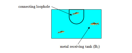
Image Courtesy of Razvan Voicu | Figure 8a. Connecting loophole – indicative scheme
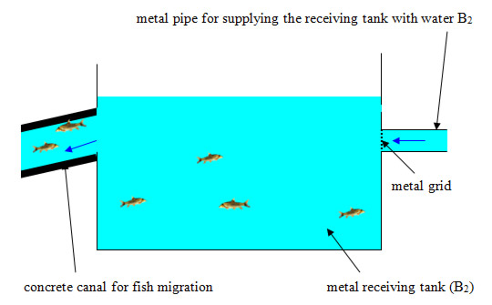
Image Courtesy of Razvan Voicu | Figure 8b. Positioning concrete canal for ichthyofauna migration – indicative scheme
Another metal drum B4 will be fixed for fish resting and recreation between the two access ways, namely the right bank and the one crossing the crest of Ișalnița Dam. This tank B4 will connect the first module of the concrete canal for fish migration to the second module passing under the way crossing the crest of the dam (Fig. 9). Therefore, the next module of the concrete canal for fish migration will pass under the road continued by a subterranean sector provided with a lighting system suitable for ichthyofauna.
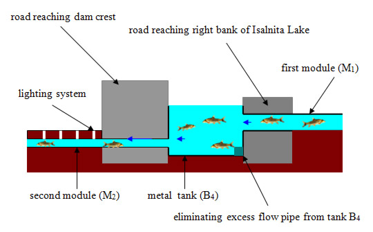
Image Courtesy of Razvan Voicu | Figure 9. Positioning metal tank B4 – indicative scheme
The flow of the first module M1 will be about 20 percent larger than the flow of the second module M2 in order to raise the water level in B4 to make a connection between the two metal tanks. The water surplus will be taken over by a pipe and discharged directly into Isalnita Lake. After crossing the dam vicinity, the concrete canal for ichthyofauna migration – the second module (M2) – will continue its path on the right bank of the Jiu River and maintain the same slope up to the confluence with the River. The fixing system of the concrete canal is achieved by means of metal dowels (Fig. 10). Ichthyofauna will reach the Jiu River into a tank fitted in the River.
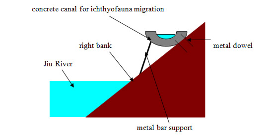
Image Courtesy of Razvan Voicu | Figure 10. Fixing concrete canal for ichthyofauna migration to bank downstream Isalnita Dam – indicative scheme
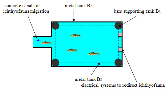
Image Courtesy of Razvan Voicu | Figure 11. Positioning tank B3 – indicative scheme
After the fish have reached tank B2, they need a system to help them reach Isalnita Lake. A metal tank B3 supporting a much smaller amount of water and built to raise fish to a level located above the Isalnita Lake level is fixed inside tank B2 by four metal bars (Fig. 11). From there, the fish are taken by a metal canal where its top is funnel-shaped and its bottom is simply flat (Fig. 12). This canal is lined with a layer of rubber.
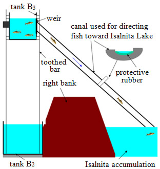
Image Courtesy of Razvan Voicu | Figure 13. Positioning the canal for fish migration in Isalnita Lake – indicative scheme
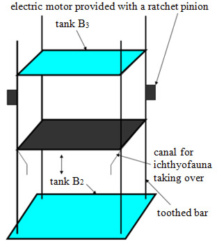
Image Courtesy of Razvan Voicu | Figure 12. Sliding tank B3 method – indicative scheme
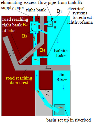
Image Courtesy of Razvan Voicu | Figure 14. General scheme for ichthyofauna migration system
Two supporting bars have thorns used to lift B3 in the canal in order to take over the ichthyofauna. Tank B3 is lifted by two electric motors symmetrically placed on the two toothed bars. The lifting systems operate according to the cog rack method. When reaching the canal for ichthyofauna taking over, a sluice automatically lifts, thus allowing the ichthyofauna to reach the channel.
Tank B3 is fixed on bars by means of metal sliding sleeves. The canal for ichthyofauna passes over the right bank of the Isalnita Lake up to 3 meters height in order not to bother people or vehicles passing along the shore (Fig. 13).
All components (Fig. 14) of the ichthyofauna migration system downstream and upstream of Isalnita Dam are automated and continuously monitored by those responsible for dam maintenance. In winter the system stops because of frost and lack of ichthyofauna migration. This system can be applied to any lake in the world without a high variation of multi-annual water level. All components can be easily replaced and have affordable prices so they can be implemented without question. This solution is designed to achieve the longitudinal connectivity of the Jiu River.
PhD, Ecotechny Engineer, National Institute of Hydrology and Water Management, Bucharest, Romania
getiiliberi@gmail.comGlobal Challenges